Saturday, February 23, 2013

Chapter 5 Topologies and Ethernet Standards

The chapter begins with explaining Logical and Simply Physical Topologies. Physical topology refers to the physical layout of the media, nodes, and devices on the network. The following are physical topologies:
  • Bus topology – consists of a single cable that connects all the nodes on the network.
  • Ring topology – each node is connected to the two nearest nodes so that the entire network forms a circle.
  • Star topology – every node is connected through a central device.

Hybrid Topologies consist of more complex combinations of topologies. Two kinds of hybrid topologies are:
  • Star-Wired Ring - This uses the physical layout of a star in conjunction with the ring logical topology.
  • Star-Wired Bus – This topology combines the star and bus formations.

Logical Topologies – refers to the way in which data are transmitted between nodes, rather than the physical layout of the paths that data take.

Backbone Networks – is the part of the network to which segments and significant shared devices connect.
  • Serial Backbone – is the simplest kind of backbone. It consists of two or more devices connected to each other by a single medium in a daisy chain fashion.
  • Distributed Backbone – consists of several intermediate connectivity devices connected to one or more central connectivity devices.
  • Collapsed Backbone – uses a router or switch as the single central connection point for multiple subnetworks.
  • Parallel Backbone – is the most robust type of network backbone. The key point is that a parallel backbone is redundant.
The text goes into great detail about the Ethernet and how it is a flexible technology and that all Ethernet networks have a common thread which is their access method. This is known as CSMA/CD. The following diagram covers the process.
                                                                 CSMA/CD Process

It covers the Ethernet standards for copper cable and fiber optic cable. The following chart is a summary of common Ethernet standards.


I found the visual depictions to be very helpful in understanding the various concepts in this chapter. The chapter was presented in a logical and organized manner which helped in grasping the material.   


Saturday, February 16, 2013

Chapter 10 - Virtual Networks and Remote Access


In this chapter we learned about Virtualization. Very simply it is the emulation of a computer on a physical system. It also could be of an operating system or an application. Virtualization offers many advantages such as:
  • Efficient use of resources
  • Cost and energy savings
  • Fault and threat isolation
  • Simple backups, recovery, and replication

However some disadvantages are:
  • Compromised performance
  • Increased complexity
  • Increased licensing costs
  • Single point of failure

 Virtual networks can consist of virtual machines on a physical server. More common are networks that combine physical and virtual elements. Virtual network components include a virtual adapter or vNIC which is required to connect to a network. Virtual bridges or ports on a switch connect to vNICs with a network, whether virtual or physical. A virtual switch is a logically defined device that operates at the data link level to pass frames between nodes. Network connection types include bridged (physical network using the host machine NIC), NAT (relies on the host machine to act as NAT device), and host-only (exchange data with each other and host only).

The text covers remote access and virtual computing through the following methods:
  • Dial-up Networking
  • Remote access servers
  • Remote access protocols
  • Remote virtual computing

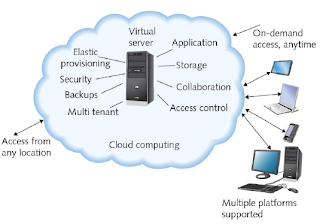
 The chapter speaks to Virtual Private Networks (VPNs) which are wide area networks that are logically defined over public transmission systems. It concludes with cloud computing (see below) which refers to the flexible provision of data storage, applications, or services to many clients over a network.


I found the material to be very informative but yet concise. There were a lot of good diagrams and illustrations to help make key points.      

Saturday, February 9, 2013

Chapter 4 Introduction to TCP/IP Protocols


This chapter is all about “Protocol”. As we have learned Protocol is the rule that governs computers and the exchange of data on the network. The protocol suite which is virtually on all networks today is Transmission Control Protocol/Internet Protocol. (TCP/IP) It is not just one protocol rather a suite of specialized protocols, including TCP, IP, UDP, ARP, and many others called subprotocols. TCP/IP has become the standard based on the following advantages:
  • It is open rather than proprietary – not owned by any company.
  • It is flexibly – can run on virtually any platform.
  • It is routable – can be interpreted by routers.

The following diagram depicts the TCP/IP model. It is essentially four layers that correspond to seven of the OSI model.


The OSI model is considered more theoretical whereas the TCP/IP is considered more practical. Understanding what functions belong to each layer of the model will be beneficial when analyzing problems.

The following is a list of subprotocols of the TCP/IP suite.  These core TCP/IP protocols operate in the transport or network layers of the OSI model and provide basic services to protocols in other layers.
  • TCP - Transmission Control Protocol provides reliable data delivery services.
  • UDP – User Datagram Protocol is a connectionless transport service.
  • IP – Internet Protocol provides how and where data should be delivered.
  • IGMP – Internet Group Management Protocol manages multicasting on networks running IPv4.
  • ARP – Address Resolution Protocol creates a database that maps the MAC address to the IP address.
  • ICMP – Internet Control Message Protocol reports on success or failure of data delivery.
The following list application layer protocols translate user requests into a format the network can read.
  • Telnet- is a terminal emulation protocol used to log on to remote hosts using TCP/IP suite.
  • FTP – File transfer Protocol is used to send and receive files via TCP/IP using ports 20 and 21.
  • TFTP - Trivial file transfer protocol that enables file transfers between computers but is simpler.
  • NTP – Network time protocol is used to synchronize clocks of computers on a network.
  • Ping – Packet Internet Groper is a utility that can verify that TCP/IP is installed.
 The most common way to express an IP addresses is the Dotted decimal notation. This refers to the shorthand convention used to represent IP addresses and makes it easy for people to read. An example of a dotted decimal IP address is 121.44.12.18. In addition to an IP address that is running IPv4, a subnet mask is assigned. A subnet mask is a special 32 bit number that when combined with the device’s IP address informs the rest of network about the segment or network to which the device is attached.

The chapter covers the assigning of IP address and DHCP (Dynamic Host Configuration Protocol) which is an automated means of assigning a unique IP address to devices on the network. It explains DHCP leasing and terminating lease process. It also, briefly talks about “private and link-local addresses” which is a means to extend the number of available addresses along with some other features.

The text also talks about Host names and DNS (Domain Name System) and sockets and ports.

There was a great deal of material in this chapter which helped provide a good understanding of Protocols and the OSI model and the TCP/IP model. This will be a good reference chapter for future use.  

Saturday, February 2, 2013

Chapter 3 – Transmission Basics and Networking Media


This chapter gets into the nuts and bolts of transmitting analog and digital signals over various medium. It begins by explaining the four fundamental properties of an analog signal. They are amplitude, frequency, wavelength, and phase.
  • Amplitude – is a measure of its strength at any given point in time.
  • Frequency – is the number of times that wave’s amplitude cycles from its starting point, it’s expressed in cycles per second or hertz (hz).
  • Wavelength – is the distance between corresponding points on a wave’s cycle.
  • Phase – refers to the progress overtime in relation to a fixed point.

 Digital signals are comprised of pulses which are positive voltages or zero voltages. This equates to a zero for no voltage present or one if voltage is present. These ones and zeroes are characteristics of the binary system. Every pulse in the digital signal is called a bit. Because digital transmission involves sending and receiving only a pattern of 1s and 0s it makes it more reliable then analogy transmission.

The text then goes into the sending of these signals and data modulation and the direction of signals. If the signal is traveling in one direction it is considered simplex. In half duplex transmission, signals may travel in both directions over a medium but in only one direction at time. Full-duplex can travel in both directions at one time. It then leads into throughput which essentially is the measure of how much data is transmitted in a given period of time, whereas bandwidth is the measure of difference between the highest and lowest frequencies.

Some common transmissions flaws are noise and attenuation. Both have negative impact on the signal strength. These flaws can be caused by a number of issues such as type of connectors used, type of wire used, and even installation methods. The chapter talks about the different types of cables in great detail along with splicing techniques.

I found the chapter to have a lot of good information. The material was understandable and presented systematically. It was a good foundation chapter.